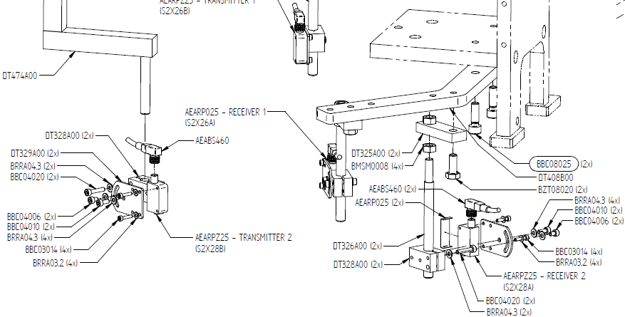
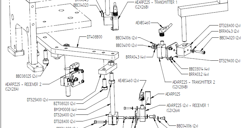
There are two spoke sensors, each comprising a transmitter and a receiver. In the illustration, they are labeled as 2x26 (sensor 1) and 2x28 (sensor 2). These sensors can be configured in two ways: F1 or F2, with F2 being the standard setup.
F1 Configuration:
F2 Configuration:
Pre-adjustment Checks:
-
Visual Inspection: Before making any adjustments, visually confirm that the receiver windows are in place.
-
No-Wheel State: In the absence of a wheel, only the green LEDs on the receivers should be illuminated. The red LED on the transmitter should always be on.
Sensitivity Adjustment:
-
Set the light/dark setting screw to its maximum (dark) position.
-
Align the transmitter and receiver:
- The light beam of sensor 1 and receiver 1 must be horizontal.
- The light beam of sensor 2 and receiver 2 must be at an angle of approximately +/- 4.5 degrees, with the transmitter lower than the receiver.
-
Adjust the sensitivity from minimum to maximum until the green LED lights up.
- Ensure that the alignment is such that around 50% of the sensitivity range is required for the green LED to illuminate. If not, make slight adjustments to achieve this balance.
These steps are essential for ensuring the spoke sensors can effectively detect spokes for smooth and accurate operation.