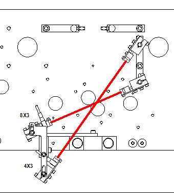
There are two spoke sensors: a transmitter and a receiver. The receivers are labeled as 8x3 and 4x3.
-
Visual Inspection: Before starting the adjustment, visually check the sensor housing for damage. Ensure that the receiver windows are in place. If no wheel is present, only the green lamps on the receivers should be lit, and the red lamp on the transmitter should always be on. Replace the sensors if necessary.
-
Wheel Selection: Use a derailleur wheel with the highest rim available for adjusting the spoke sensors (standard maximum = 32mm).
-
Machine Sequence Setup:
- Navigate to TEST MACHINE SEQUENCE.
- Set the cursor in front of the line TURN WHEEL.
-
Wheel Placement:
- Place the derailleur wheel in the input rail with the derailleur gear side (the "flat" side) on the left when seen from the operating panel.
- Stop the wheel from turning by pressing <F1>.
-
Sensitivity Adjustment:
- Set the light/dark setting screw to its maximum (dark) position.
- Turn the wheel slowly by hand in the direction of rotation and observe whether the receiver lamps (red and green) light up when a spoke passes.
- Continue turning the wheel until a transmitter and receiver "look" between two spokes.
- Adjust the receiver's sensitivity using the set screw so that only the green lamp lights up.
- Turn the wheel again to ensure both lights illuminate when a spoke passes.
- Adjust receiver 8x3 if necessary so that it detects the spoke about 10 mm before the center of the drive roller. Tighten the M8 fixing bolt after adjustment.
-
Sensor 4x3 Adjustment:
- Sensor 4x3 detects whether a left or right spoke passes sensor 8x3.
- For a left spoke, the sensor 4x3 light should first go on and then off again, followed by the 8x3 light.
- For a right spoke, it's the opposite (8x3 first, then 4x3).
- Adjust the height of the sensors accordingly:
- Sensor 8x3 should be set just above a 32mm high rim.
- Sensor 4x3 should be adjusted 5-8mm lower.
- Tighten the M8 fixing bolt after adjustment.
-
Check Adjustments:
- Verify the adjustments by pressing <F1> to turn the wheel.
- You should see a regular pattern on the screen: "LRLRLRLRLRLRLRLRLRLRLRLRLRLRLRLRLRLRLRLRLRLRL" at both high and low speeds.
-
Index Wheel:
- Move the cursor one line down.
- Select INDEX WHEEL by pressing <ENTER>.
- Each time you press <ENTER>, the wheel is indexed one pair of spokes further.
- After indexing, ensure that the drive roller's centerline is in the middle between the spokes.
-
Testing:
- Test the setting on different types of wheels.
-
Repeating Adjustments: If the result is not satisfactory, repeat the adjustments as described above. If issues persist, contact Holland Mechanics for support.
-
Exiting the Program:
- To exit the program, move the cursor to the top line and press <MENU>.
These steps should help you adjust the spoke sensors accurately.