![HMLogo RGB high res.png]](https://knowledgebase.hollandmechanics.com/hs-fs/hubfs/HMLogo%20RGB%20high%20res.png?height=48&name=HMLogo%20RGB%20high%20res.png)
This tool is used to accurately adjust the wheel so that the rim is correctly centered in relation to the hub.
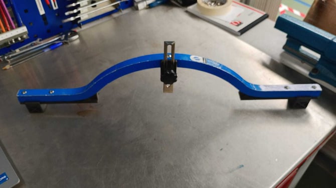
After the wheel has been completely assembled on the lacing machine, check the wheel using the Dish Tool as follows:
-
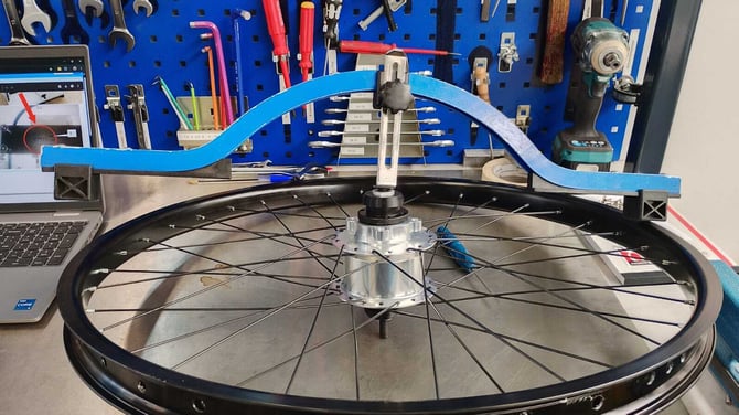
Position the dish tool on the wheel as shown. Adjust the plastic support so that it makes exact contact with the rim profile. In this first image, the dish tool has been placed on the rim without making any adjustments.
-
Adjust the upper clamp. However, this adjustment will depend on the model of your dish tool, as each model has a different adjustment system. Regardless of the model, all dish tools must be positioned as shown in the image below, with the contact points fully touching the hub and the nut.
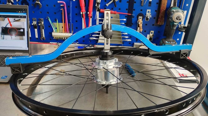
Once the adjustment is complete, lock the movement of the dish tool axle. Then, invert the wheel and compare the opposite side.
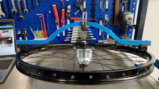
Now, on this side, we can see that the axle, which on the opposite side was fully touching the hub axle nut, now has a different height compared to the other side.
NOTE:
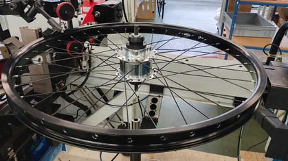
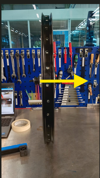
Before making any adjustment, it is important to understand how the system works. The machine divides the rim into four groups: Group 1, Group 2, Group 3, and Group 4. If the values of the groups that are positioned together are increased, which should always be Group 1 and Group 2, these two groups will become tighter. As a result, the side of the rim that is facing upwards on the machine, as shown in this image, will tend to move further inward, closer to the hub flange.
-
Rim in Working Position on the Machine
-
The rim has been removed from its working position and placed vertically for better understanding.
This behavior will apply to both sides of the rim, on the left side as well as on the right side.
In summary, increasing the spoke tension on one side of the wheel will always affect the position of the opposite side. Before making any adjustment, it is important to select only one side to work on. Adjusting both sides at the same time can create confusion. As a general rule, always work with only one pair of groups:
- Group 1 and Group 2, or
- Group 3 and Group 4
Adjusting both pairs of groups together should only be done in specific situations. The recommended method is to always work with one pair of groups at a time.
Another important tip is that there is a difference between front and rear wheels. Front wheels usually have both sides with the same tension, making the symmetry clearly visible. Rear wheels normally have one side with higher tension than the other. This can be easily noticed because one side of the wheel has a more pronounced curve compared to the opposite side.
For this reason, the use of the dish tool is extremely important to ensure the correct wheel alignment and verify that the rim is properly centered in relation to the hub.
Reference Values
The values below are only examples. They are not fixed adjustment values.
Front Wheel
Usually, all groups have the same value in the lacing machine screen:
- Group 1 = 10
- Group 2 = 10
- Group 3 = 10
- Group 4 = 10
Some rims may have a small difference:
- Group 1 = 10
- Group 2 = 10
- Group 3 = 9
- Group 4 = 9
This can be normal depending on the rim design.
Rear Wheel
Rear wheels normally have different values between the groups:
lacing machine screen
- Group 1 = 30
- Group 2 = 30
- Group 3 = 15
- Group 4 = 15
This happens because the rear hub has a different position between the two sides.
The values shown are only examples. The correct adjustment depends on the rim, hub, and wheel model. Always verify the final result using the dish tool.